Dead SDR Society
building an RF transmitter, capturing the signal, and killing my RTL-SDR in the process
RF transmissions are everywhere and most are unencrypted. Walked through building a 868 MHz transmitter with Arduino and RFM12B, capturing it with RTL-SDR, decoding with GNURadio and Inspectrum. Then I fried the SDR.
why radio
There is an entire attack surface most security researchers ignore because it does not involve a browser or an API: the electromagnetic spectrum.
Garage doors. Smart meters. Key fobs. Temperature sensors. Baby monitors. All of these broadcast data on frequencies you can receive with $30 of hardware. Most do not encrypt. Some authenticate with a rolling code that has not been broken. Many do not.
This is the story of building a transmitter, capturing it, and trying to decode it before my RTL-SDR met an unfortunate end.
the basics: modulation
Before touching hardware, the theory. Any wireless signal encodes data by varying one of three properties of a carrier wave:
Amplitude Modulation (AM): vary the signal strength. High amplitude = 1, low = 0. Simple, noisy, used in early radio.
Frequency Modulation (FM): vary the frequency. 868.01 MHz = 1, 868.00 MHz = 0. More noise-resistant than AM.
Phase Modulation (PM): vary the phase shift relative to a reference signal. More complex, used in modern digital comms.
For this experiment: ON/OFF Keying (OOK), a degenerate form of AM. Transmitter on = 1, transmitter off = 0. The simplest possible encoding and the most common in cheap IoT devices.
hardware setup
the transmitter
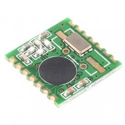
RFM12B from Hope RF, a sub-GHz transceiver module. Cheap (~$4), well-documented, supported by Arduino via the JeeLib library. Operates at 433 MHz, 868 MHz, or 915 MHz depending on region and model.
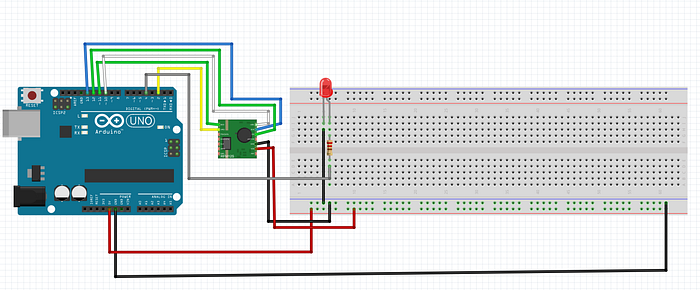
Connect to an Arduino UNO via SPI:
RFM12B       Arduino UNO
──────────   ───────────
SDI    →     MOSI (pin 11)
SDO    →     MISO (pin 12)
SCK    →     SCK  (pin 13)
NSEL   →     SS   (pin 10)
IRQ    →     pin 2
VCC    →     3.3V
GND    →     GND
Note: RFM12B is a 3.3V device. The Arduino runs at 5V. A level shifter on the SPI lines is technically required. Many people skip it and it works until it does not. Use a voltage divider or a proper level converter if you care about your hardware.
The antenna is a quarter-wave wire:
λ/4 at 868 MHz = (300 / 868 / 4) × 1000 mm ≈ 86.4 mm
Solder an 86mm wire to the antenna pad. Tolerance of a few millimeters does not matter much at these frequencies.
the Arduino sketch
#include <JeeLib.h>

#define FREQUENCY RF12_868MHZ
#define GROUP     212
#define NODE_ID   1

void setup() {
    Serial.begin(57600);
    rf12_initialize(NODE_ID, FREQUENCY, GROUP);
    Serial.println("[*] RFM12B initialized at 868 MHz");
}

void loop() {
    // 4-byte payload transmitted every 500ms
    struct {
        uint8_t  node;
        uint16_t counter;
        uint8_t  crc;
    } __attribute__((packed)) payload;

    static uint16_t cnt = 0;
    payload.node    = NODE_ID;
    payload.counter = cnt++;
    payload.crc     = payload.node ^ (payload.counter & 0xFF);

    rf12_sendStart(0, &payload, sizeof(payload));
    rf12_sendWait(2);  // wait for transmission, then sleep radio

    Serial.print("[>] sent packet #");
    Serial.println(cnt);

    delay(500);
}
This sends a 4-byte structured payload at 868 MHz every 500ms. The counter field increments each transmission so you can identify individual packets in the capture. rf12_sendWait(2) blocks until done and puts the radio into low-power mode between transmissions.
the receiver: RTL-SDR
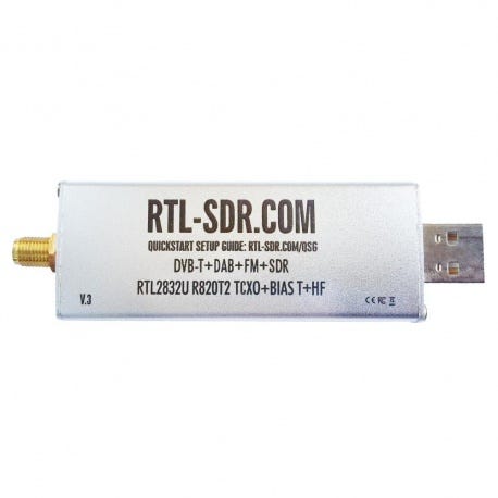
The RTL-SDR is a repurposed digital TV receiver used as a wideband software-defined radio. Costs $25-30. Covers roughly 25 MHz to 1.7 GHz with some gaps. Enough to see 868 MHz.

If you have already killed your RTL-SDR (see: the end of this post):
- HackRF One: 1 MHz to 6 GHz, full-duplex, ~$300
- LimeSDR Mini: similar range, better RF performance, ~$150
- SDRPlay RSP1A: 1 kHz to 2 GHz, excellent for HF, ~$110
- PlutoSDR: 70 MHz to 6 GHz, full-duplex, ~$100
capturing the signal
step 1: find the frequency with GQRX
sudo apt install gqrx-sdr
gqrx
Set center frequency to 868.000 MHz. Set sample rate to 2.4 MSPS. Enable the waterfall view (spectrum over time).
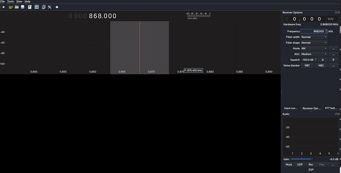
When the Arduino transmits, you will see a bright spike in the waterfall repeating every ~500ms. This confirms the hardware works and tells you the exact frequency offset from 868 MHz center.
step 2: record IQ samples with GNURadio
Build this flowgraph in GNURadio Companion:
RTL-SDR Source        File Sink
center: 868 MHz   →   filename: capture.bin
sample rate: 2.4M     type: complex float32
gain: 40 dB           unbuffered: yes
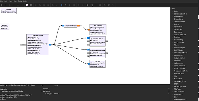
Run for 10-15 seconds while the Arduino transmits. Stop. The file contains raw complex (IQ) samples representing the full band around 868 MHz. It is not demodulated yet, just raw RF energy as a stream of (float32 I, float32 Q) pairs.
File size: 2.4M samples/s x 8 bytes/sample x 10s = ~192 MB
step 3: visualize with Inspectrum
sudo apt install inspectrum
inspectrum capture.bin -r 2400000
Set the sample rate to 2.4 MSPS in the UI. The spectrogram view shows frequency on the Y axis and time on the X axis. You should see the OOK signal: a repeated pattern of bright (transmitter on) and dark (transmitter off) blocks.
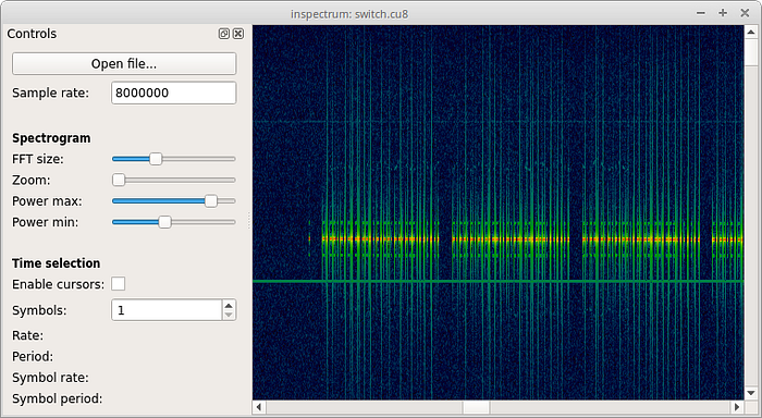
Enable the power threshold. Inspectrum shows a red/green overlay indicating where the signal crosses the threshold. This is your bit stream.
Set the symbol rate to match the RFM12B default baud rate (4800 bps). Each cell in the symbol grid should align with one bit period (1/4800s = ~208 microseconds). Read off the pattern.
For OOK: power above threshold during the symbol period = 1, below = 0.
You should see something like:
preamble: 10101010 10101010   (sync pattern)
sync word: 2D D4              (RF12 default)
payload:   01 00 00 00        (node=1, counter=0, crc=1)
step 4: cross-check with Audacity
GNURadio can also output demodulated audio. Add an AM demodulator to the flowgraph:
RTL-SDR Source  →  Low Pass Filter  →  AM Demod  →  Audio Sink
                   cutoff: 10k Hz
                   transition: 1k Hz
The AM-demodulated OOK signal sounds like rhythmic clicks. In Audacity, load the audio and measure the pulse widths in microseconds. At 4800 bps each pulse is ~208 microseconds. Verify this matches what Inspectrum showed.
step 5: decode with URH
Universal Radio Hacker is better than Inspectrum for full protocol analysis:
pip install urh
urh
Import the .bin file. URH auto-detects the modulation, symbol rate, and bit pattern. It can identify the preamble, sync word, and frame structure automatically. It also has a protocol analyzer that can decode common IoT protocols.
what you can do with this
replay attacks
If a device authenticates with a fixed code (no rolling counter), capturing and replaying is trivial with HackRF:
# record
hackrf_transfer -r capture.bin -f 868000000 -s 2000000

# replay
hackrf_transfer -t capture.bin -f 868000000 -s 2000000 -x 40
This works against:
- Old garage door remotes (pre-2000, fixed code)
- Some cheap alarm sensors
- Many 433 MHz smart home devices with no authentication
It does not work against:
- KeeLoq rolling codes (modern car key fobs)
- Properly implemented HOTP/TOTP
- AES-encrypted payloads
frequency survey before a physical engagement
# rtl_power: scan 300 MHz to 1 GHz, 1 MHz steps, 10-second averages, 60-second total
rtl_power -f 300M:1G:1M -g 40 -i 10 -e 60 survey.csv

# visualize
python3 -c "
import csv, sys
data = list(csv.reader(open('survey.csv')))
for row in data[:5]:
    print(row)
"
A 60-second passive scan maps every RF source active in the environment: access control readers, building automation, HVAC sensors, keyless entry. Useful intelligence before walking in.
signal identification
The Signal Identification Guide covers hundreds of modulation types with audio samples and waterfall screenshots. If you see something unfamiliar in the waterfall, match it here before spending time reversing it.
what went wrong
I killed my RTL-SDR.
I connected an external antenna near a strong transmitter. The LNA at the RTL-SDR input has no protection diode. Enough RF energy burns the front end. The dongle still powers up, still shows in lsusb, but the sensitivity is gone. Everything is noise.
Lessons:
- Attenuator: put a 10-20 dB inline attenuator before the SDR when near strong transmitters
- SAW filter: a narrowband filter centered on your frequency of interest blocks out-of-band energy that damages the LNA
- Separation: keep the transmitter physically away from the receiver during testing. Opposite ends of the room minimum
The RTL-SDR has no recovery from a blown LNA. Buy a new one and add the attenuator this time.
references
- RTL-SDR Blog Getting Started Guide
- GNURadio Tutorials
- Inspectrum GitHub
- Universal Radio Hacker
- JeeLib Arduino Library
- Signal Identification Guide
- RTL-SDR protection circuits